Flashing Tasmota Firmware on Wifi Smart Switches Sonoff Basic S20 SV
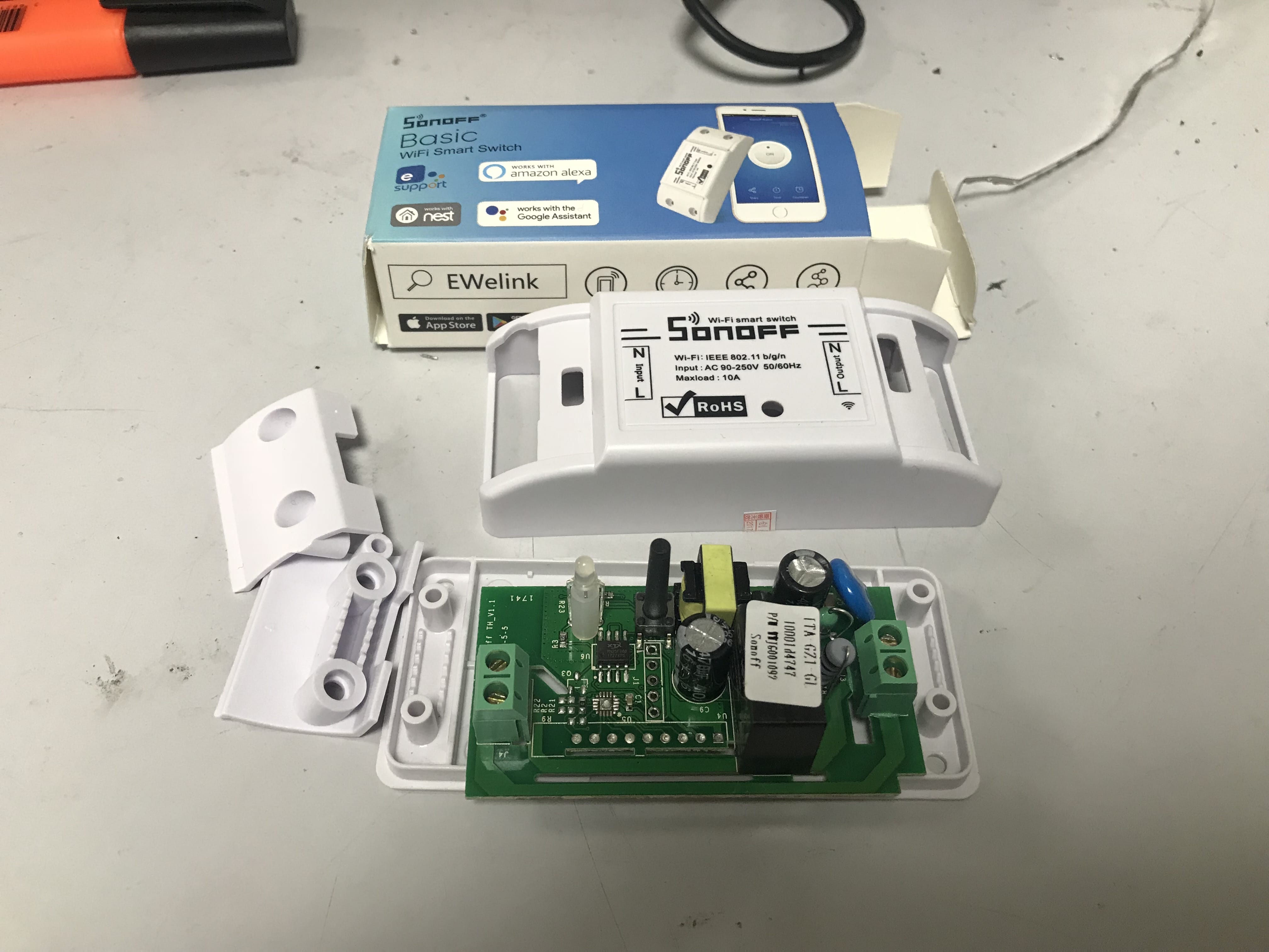
The Sonoff devices by https://www.itead.cc/ are an excellent little range of modules for building your own Smart Home setup. They are pretty well built, CE and RoHS marked and implement what is essentially a WiFi operated switch/relay circuit based on the extremely versatile ESP8266. See here for a full circuit schematic. It can handle up to 10A load so could be used for lights, lamps, speakers, ventilation, small appliances – anything.
They come in the form of inline 90-240V AC switches (Basic), UK/EU/US 90-240V AC Plug Sockets (S20), 5-24V DC inline switches (SV – Safe Voltage) and many more options with different sensors, fitments and even dual and quad switchable relay banks. As I use any of the variants, I will update this guide to include them.
They are available from a few places in the UK via the usual places. E.g.
Amazon:
Sonoff Basic
Sonoff S20
Sonoff SV
Or if you don’t mind waiting a little longer, they are available from China a bit cheaper but will take around 2 weeks to arrive:
eBay:
Sonoff Basic
Sonoff S20
Sonoff SV
All the devices come loaded with software that allows operation of the switch via the free cloud service run by Itead and their free app for iOS and Android. This includes Alexa, Nest and other popular Smart Home integration as standard. I, like many others, didn’t want to use on this service so opted to flash the software to one of the available alternatives – in my case, Tasmota. As the ESP8266 is a popular platform found on a number of Arduino based project, there is a lot of support and customisation options thanks to things like NodeMCU and integration into popular Smart Home protocols like MQTT. It ultimately means these devices can easily become part of a fully custom built automated smart home setup without the big expense.
What You Need
- A Sonoff Device (see lists above)
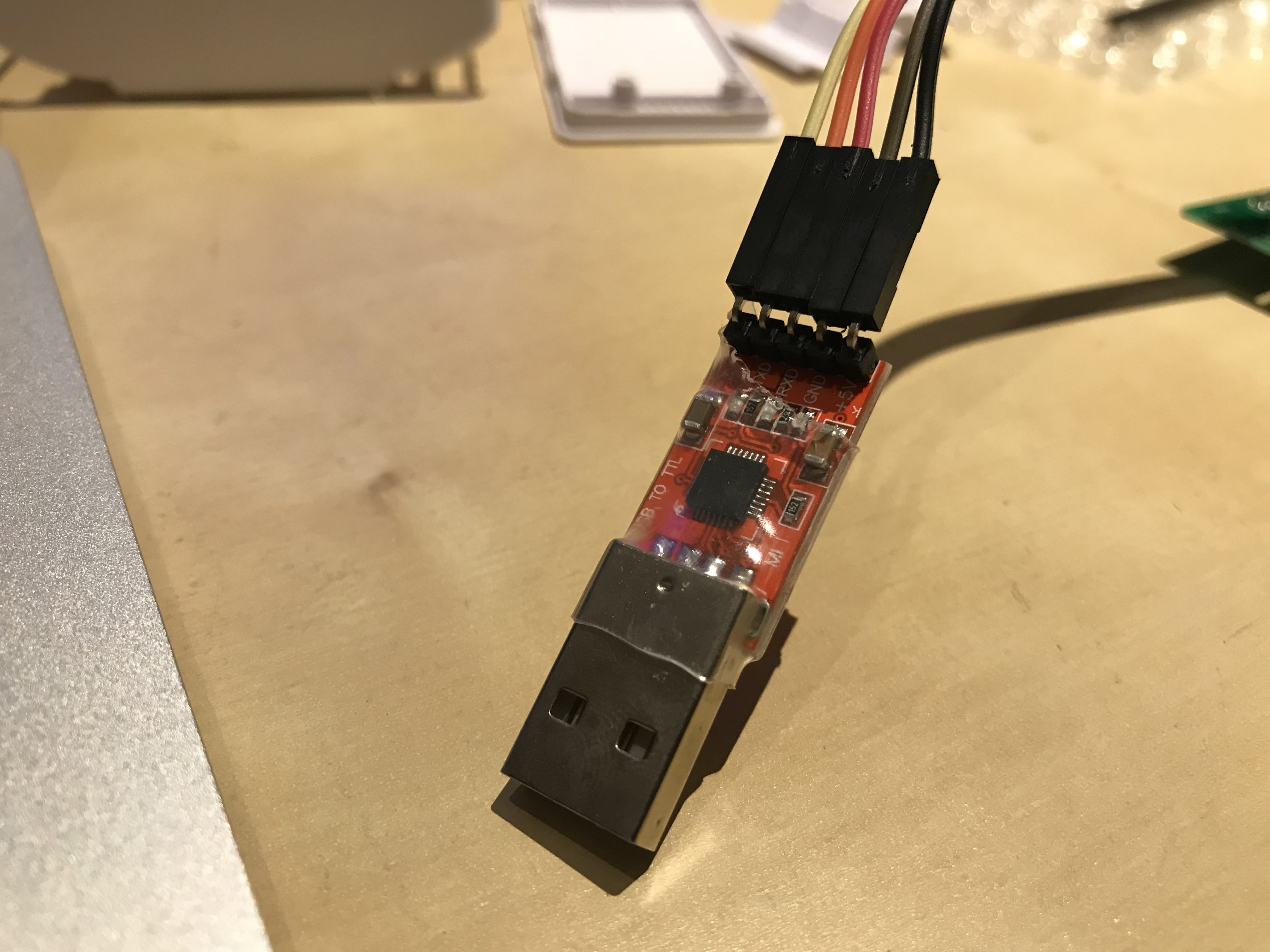
- A USB 3.3V FTDI programmer. (Example)
IMPORTANT: Must be capable of operating with a 3.3V VCC (switchable or fixed) – many of these only support 5V and will probably kill the ESP8266. - Some Dupont Cable (Example)
- 2.54mm pitch single row headers (Example)
- A soldering iron with a fine tip and solder (Example)
- A PC or Laptop with an appropriate IDE installed. I use a Mac so decided to go with Microsoft Visual Studio Code with Platform.io installed as an extension. The instructions with Tasmota are very good, so would advise reading them for alternatives and setup instructions depending on your platform.
Getting At The Internals
You need to get at the circuit to attach some header pins to reprogram these.
In each of the pictures you can see the exposed top side of the circuit and the position of the 4 (or 5) holes where the single row 2.54mm header pins should be soldered in.
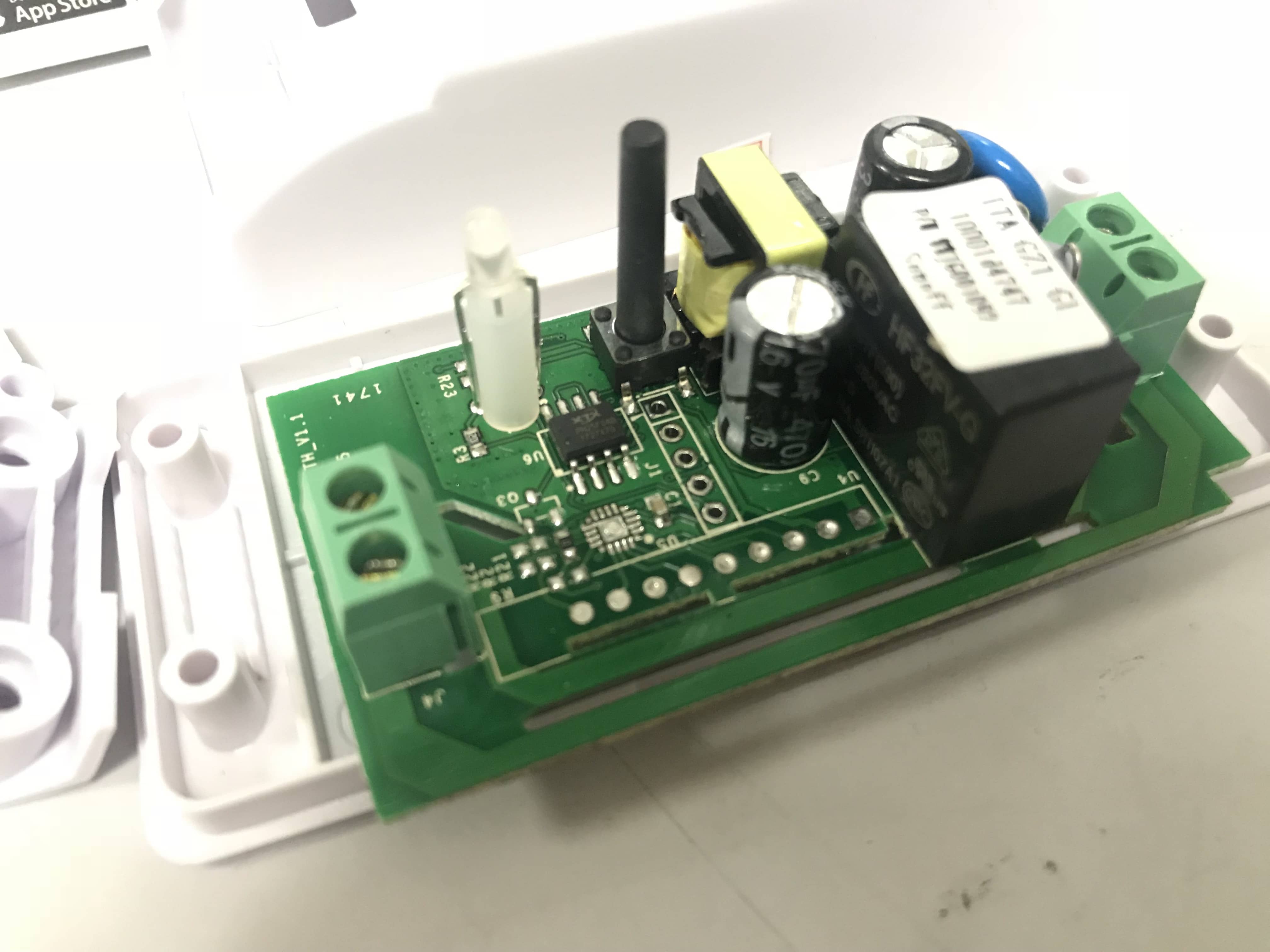
Sonoff Basic – The lid pops off and the 5 holes are to the left of the electrolytic capacitor in the middle of the board.


Sonoff S20 – Remove 3 screws on the rear (one under the small security sticker) and the 4 connector holes are just above the bright blue capacitor. You need to undo two more screws on the PCB near the plug socket to remove the board from the enclosure.

Sonoff SV – 4 pins at the very right of this board (I’ve already soldered the header in this picture)
Solder On the Interface Header
Carefully solder a strip of the appropriate number of 2.54mm header pins to the PCB – solder from the underside (first image below shows underside of Sonoff Basic, second image the rear of the S20).


Connecting The Programming Interface
Ensure the programmer is a 3.3V VCC supply. Connect the VCC and GND pins on the interface to the Sonoff and make sure the TX and RX pins are reversed (i.e. TX -> RX, RX -> TX).

Note that in the case of the Sonoff Basic, the pins are marked and the 5th pin is an unused GPIO pin (GPIO14) which remains unused in normal application.

For the S20, the pins/holes are unmarked. The bottom most pin is the VCC 3.3V. The pins are otherwise in the same order as the Basic.
Load Project in IDE and Customise
Download the Tasmota firmware (or equivalent) source from Git and load the project into your selected IDE. Edit the relevant source code to change parameters to match your intended environment settings (e.g. IP Address and Subnet, WiFi connection settings, password, MQTT topic, group and any other settings you need).

Program the Device
Press and hold down the physical button on each of the PCBs while connecting/powering on the USB interface. This puts the unit into programming/receive mode.
Compile and send the firmware according to your IDE. It should take no more than a minute or so.

Reboot the Sonoff once sending is complete (remove and reapply power without holding down the button).
Test
Navigate to the web page at the IP Address previously specified

You should be able to toggle the relay on and off with an audible click and LED light ON/OFF accordingly.
Now it just needs wiring in to operate a device…and integrating into a more user friendly interface with a proper smart home automation backend.
Useful Tweaks
Common (optional) commands I use after flashing on some modules:
(Note that these can be entered in the web console or as web queries or tweaked in the initial source code before programming – they are persistent either way but if you program them in the source, they will be default if the module is reset)
ledstate 0 (prevents use of the LED as much as possible)
poweronstate 1 (powers the relay ON when power applied as the default state)
sleep 250 (the maximum sleep cycle for lowest possible idle power consumption – you may need to tweak this depending on requirements as unexpected delays may be experienced if any GPIO functions are used)
The full console command list can be found here.


