Electronic Delay Latch
The Background
A while ago, I built a PC and used an All-in-Wonder Radeon 9700 Pro graphics card. For those who aren’t too familiar with them, read here. They were one of the first cards to require an external power connector to provide extra juice that couldn’t be drawn from the AGP bus.
Coupled with this card, I used an Enermax 435W PSU, which was easily sufficient in terms of power output and was a good, reliable brand. However, I ran into problems with the computer booting from cold.
The fans would start spinning for a brief second before everything died. In my fault finding, I removed the power connector from the graphics card and the system booted up fine and displayed a message telling me to plug the card connector in. Voila, everything works!
Well, except that every time I want to turn the computer on, I have to unplug the card…not so good.
I came to the conclusion that it was the power supply’s surge protection of some sort kicking in and preventing the card from drawing the power it needed at boot up. (I tried a smaller, no name PSU and it worked fine. However, not wanting to destroy my hardware by using a cheap PSU, I needed a different solution).
The Delay
Since the system worked fine when the power was supplied to the card a few seconds after a cold boot, I figured the only sensible thing would be to simulate this delay electronically. In other words, have a system that sits between the card and the power connector that creates a delay between when I press the power button on the PC to power getting to the card.
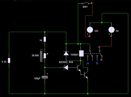
After a bit of researching and developing and testing, I came up with the following circuit:
Components:
(1x) TIP122 Darlington Pair Transistor
(1x) 47K Variable Linear Pot Resistor
(1x) 100uF 16V Electrolytic Capacitor
(1x) 5.1K Resistor
(1x) 1K Ressitor
(1x) 6V8 Zener Diode
(1x) 1N4001 Diode
(1x) 12V 6A (Double Pole Double Throw) DPDT Relay
Putting It Together
Assemble the circuit using either a bit of strip board, or if you have access to PCB fabrication facilities, feel free to use the following mask, but you’ll have to work out where things go for yourself…

Connect everything up and run a test just to make sure it’s all working as it should. Remember, Yellow = +12V, Red=+5V, Black =0V. Connect it to the PSU and you should hear a definite ‘click’ as the relay latches and turns on. Make sure the transistors aren’t melting and that the capacitors aren’t exploding. Test it with nothing connected to the output just yet – use a multimeter to measure the outputs – they should read 12V and 5V when on.
When you are confident that it is working as it should be, connect it to your graphics card and enjoy never having to mess about with the power connector ever again!
How It Works
When the power button is pressed on the front of the computer (referred to as S1 in the schematic above), the 1k and the variable 47k resistor network allows some current to flow through and get stored in the capacitor.
As this charge builds up, the voltage at the Zener diode begins to rise. When it reaches 6.8V, the diode immediately begins to conduct, turning on the Darlington Pair Transistor.
This transistor pair is isolated from the main power circuitry using a power relay, which is in turn, switched on – causing the main 12V and 5V power lines to effectively connect straight to the graphics card via points A and B marked on the schematic. For reference, the additional diode is in place to protect the transistors.
The delay period can be varied to suit the application using the variable resistor.
Disclaimer
This is only a guide.
You may use the information in the article to help you solve problems you are having with your graphics cards or other related issues, but I AM NOT responsible for anything you blow up or damage. All the work you do is at your own risk. Remember: research and understand what you are doing. If in doubt, don’t do it. If you have any questions, post here or in the forum and I can try and help.
Cheers.