Samsung Monitor Power PCB Capacitor Repair
If you have a Samsung LCD monitor that has started taking ages to turn on, flickers, has a flashing blue power button with a black screen (i.e. not the “no input” message), makes a high pitched whining noise or even fails to turn on at all, the problem is likely to lie with the power circuit board (IP-45130A, pictured below) inside. This board is used in many Samsung monitors including but not limited to the 226BW, 225BW and 223BW.

Samsung used really poor quality capacitors made by CapXon on these boards which, over time, will have deformed and stopped performing within tolerances. I repaired the board in my Samsung SyncMaster 226BW monitor which had gotten progressively worse to the point where it would not power on at all. This guide outlines the process.
Parts Required
There are a total of 6 capacitors that need are common culprits to be replaced. Referring to the picture above they are the two in the middle of the board and the four towards the bottom right hand side. Although these are the ones which most often will have failed (on my board, they had all started bulging), it is worth visually inspecting the others at the same time. For example, the large capacitor lying flat on the PCB rarely fails so I left that one alone. The replacements I used are linked below for examples of what sort of thing to get to replace the bad ones with. I got them from Farnell here in the UK.
C111, C112, C114, C316, C317
820µf 25v 105°C, 10mm D x 20mm H (PANASONIC EEUFR1E821)
PANASONIC – EEUFR1E821 – CAPACITOR, RADIAL, 25V, 820UF
C113
330µf 25v 105°C, 10mm D x 12.5mm H (PANASONIC EEUFM1E331)
PANASONIC EEUFM1E331 Capacitor Radial 25v 330uf QTY: 1
Obviously, a soldering iron, solder and the ability to solder would be most useful…
50w Variable Temperature Adjustable Controlled Solder Station Iron Gun Soldering Kit Set
Solder with Cored Flux 100g 60/40 Tin Lead Resin 0.7mm
Disassemble the Monitor
Observe the regular precautions of disconnecting power and earthing before taking the unit apart.
– Remove the three large screws that hold in the base/stand and slide the stand out
– Remove the three smaller screws at the lower edge of the rear of the monitor
– Work your way around the plastic rear cover and prise the shell apart
– Disconnect the four cables running into the inverter side of the power board
– Disconnect the ribbon cable running into the top of the LCD panel
– Disconnect the small connector running from the control/power button PCBs
– Remove the shielding and remove the metal frame that houses the Power PCB and Input/Processing PCB
– On the underside of the metal frame, disconnect the cable that runs between the two PCBs
– Undo the three screws that hold the Power PCB to the metal frame
The Bad Capacitors
Once the board has been removed inspect the capacitors for irregularities.

Here you can see the tops of the capacitors bulging, rounded outwards – a sign that they are failed or failing. They should be flat.


One of the evil 820µF CapXon capacitors and the two central capacitors removed from the PCB.
The Replacement Capacitors


One of the new replacement 820µF Panasonic capacitors and the underside of the PCB. Make sure you observe the correct orientation when putting these in. There are indications on both sides of the PCB and a strip down the side of the capacitor itself to indicate the negative connection/terminal.
The Result

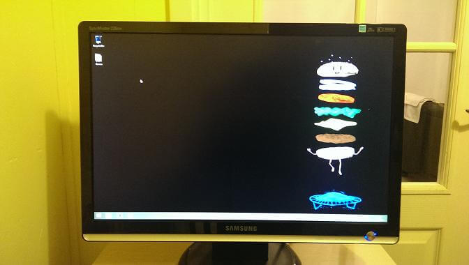
All bad capacitors replaced and the monitor reassembled (just follow the reverse of the brief dis-assembly instructions above).
Footnote: When testing, I find that double checking you’ve plugged in the power cable at both ends and turned on the switch at the wall is a good starting point…


Very helpful article, purchased spares from RS. Worked like a dream.
Monitor working as good as new
Glad you found it useful :)